Moxa Mfg Mini-Store MOXA Major Lines
Moxa IMC-101-M-ST-T 10/100BaseT(X) to 100BaseFX, multi mode ST, smart relay output alarm, Link-Fault-Pass-Through, w/ -40~75 C
MOXA Major LinesMfg Part Number: IMC-101-M-ST-T , Item #: 351286


In Stock: 5
 , PO and Wire.
Related Model(s):
10/100BaseT(X) to 100BaseFX, multi mode SC, smart relay output alarm, Link-Fault-Pass-Through

10/100BaseT(X) to 100BaseFX, multi mode SC, smart relay output alarm, Link-Fault-Pass-Through, w/ -40~75 C

10/100BaseT(X) to 100BaseFX, multi mode ST, smart relay output alarm, Link-Fault-Pass-Through

10/100BaseT(X) to 100BaseFX, single mode SC, smart relay output alarm, Link-Fault-Pass-Through

10/100BaseT(X) to 100BaseFX, single mode SC, smart relay output alarm, Link-Fault-Pass-Through, w/ -40~75 C
| Introduction |
||||||||||||||||||||||||||||||||||||||||||||||||||||||||||||||||||||||||||||||||||||||||||||||||||||||||||||||||||||||||||||||||||||||||||||||||||||||||||||||||||||||||||||||||||||||||||||
|
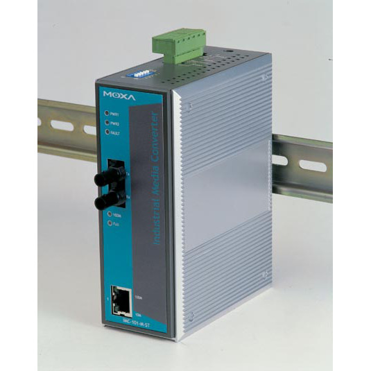
IMC-101
Series
IMC-101 has been designed for use in harsh industrial environments, such as in hazardous locations (class 1 division 2 or zone 2), and complies with FCC, TÜV, UL, and CE standards. The IMC-101 Series is available in models that support an operating temperature of 0 to 60°C, and an extended operating temperature of -40 to 75°C. In addition, IMC-101 products are subjected to a 100% burn-in test, guaranteeing that they can be used in industrial automation control environments. Link Fault Pass-Through IMC-101's "Link Fault Pass-Through" feature overcomes a problem encountered when using traditional media converters. The problem is this. When one side of the link fails, the other side continues transmitting packets, and then waits for a response that never arrives from the disconnected side. What IMC-101 does is force the link to shut down as soon as it notices that the other link has failed, giving the application software a chance to react to the situation. Redundant Power Inputs IMC-101 provides two power inputs that can be connected simultaneously to live DC power sources. If one power input fails, the other source acts as a backup, and automatically satisfies IMC-101's power needs. Relay Output Alarm by Port Break, Power Failure IMC-101 provides relay contact outputs to warn technicians on the shop floor when the power fails or a port link is disconnected, so they can respond quickly with appropriate emergency operation procedures. |
||||||||||||||||||||||||||||||||||||||||||||||||||||||||||||||||||||||||||||||||||||||||||||||||||||||||||||||||||||||||||||||||||||||||||||||||||||||||||||||||||||||||||||||||||||||||||||
| Features |
||||||||||||||||||||||||||||||||||||||||||||||||||||||||||||||||||||||||||||||||||||||||||||||||||||||||||||||||||||||||||||||||||||||||||||||||||||||||||||||||||||||||||||||||||||||||||||
|
||||||||||||||||||||||||||||||||||||||||||||||||||||||||||||||||||||||||||||||||||||||||||||||||||||||||||||||||||||||||||||||||||||||||||||||||||||||||||||||||||||||||||||||||||||||||||||
| Specifications |
||||||||||||||||||||||||||||||||||||||||||||||||||||||||||||||||||||||||||||||||||||||||||||||||||||||||||||||||||||||||||||||||||||||||||||||||||||||||||||||||||||||||||||||||||||||||||||
|
||||||||||||||||||||||||||||||||||||||||||||||||||||||||||||||||||||||||||||||||||||||||||||||||||||||||||||||||||||||||||||||||||||||||||||||||||||||||||||||||||||||||||||||||||||||||||||
| Ordering Information |
||||||||||||||||||||||||||||||||||||||||||||||||||||||||||||||||||||||||||||||||||||||||||||||||||||||||||||||||||||||||||||||||||||||||||||||||||||||||||||||||||||||||||||||||||||||||||||
|
||||||||||||||||||||||||||||||||||||||||||||||||||||||||||||||||||||||||||||||||||||||||||||||||||||||||||||||||||||||||||||||||||||||||||||||||||||||||||||||||||||||||||||||||||||||||||||
| Optional Accesories |
||||||||||||||||||||||||||||||||||||||||||||||||||||||||||||||||||||||||||||||||||||||||||||||||||||||||||||||||||||||||||||||||||||||||||||||||||||||||||||||||||||||||||||||||||||||||||||
|

Specification
| Interface | |
| DIP Switches | 100BaseFX Full/Half duplex selection, port break alarm mask |
| Fiber Ports | 100BaseFX (SC/ST connectors) |
| LED Indicators | PWR1, PWR2, FAULT, 10/100M (TP port), 100M (Fiber port), FDX/COL (Fiber port) |
| Alarm Contact | One relay output with current carrying capacity of 1 A @ 24 VDC |
| RJ45 Ports | 10/100BaseT(X) |
| Power Requirements | |
| Overload Current Protection | 1.1 A |
| Reverse Polarity Protection | Present |
| Input Voltage | 24 VDC (12 to 45 VDC), redundant inputs |
| Input Current | 160 mA @ 24 VDC |
| Connection | Removable terminal block |
| Technology | |
| Standards | IEEE 802.3 for 10BaseT IEEE 802.3u for 100BaseT(X) and 100BaseFX |
| Environmental Limits | |
| Operating Temperature | Standard Models: 0 to 60°C (32 to 140°F) Wide Temp. Models: -40 to 75°C (-40 to 167°F) |
| Storage Temperature | -40 to 85°C (-40 to 185°F) |
| Ambient Relative Humidity | 5 to 95% (non-condensing) |
| MTBF (mean time between failures) | |
| Time | 401,000 hrs |
| Database | MIL-HDBK-217F, GB 25°C |
| Physical Characteristics | |
| Weight | 630 g |
| Dimensions | 53.6 x 135 x 105 mm (2.11 x 5.31 x 4.13 in) |
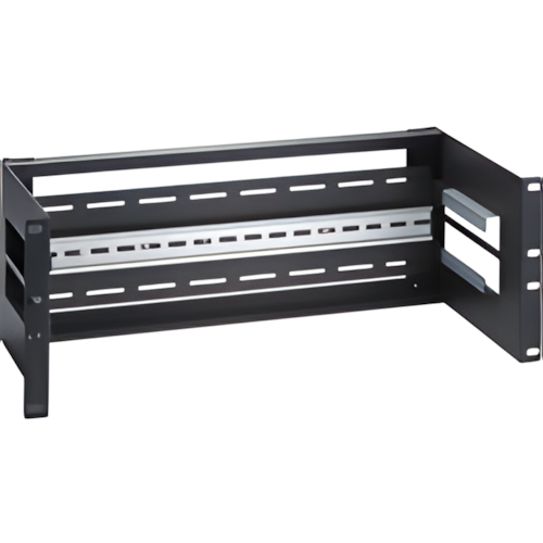
| Installation | DIN-Rail mounting, wall mounting (with optional kit) |
| Housing | Metal, IP30 protection |
| Standards and Certifications | |
| EMI | FCC Part 15 Subpart B Class A, EN 55022 Class A |
| Safety | UL 508, UL 60950-1, EN 60950-1 |
| Hazardous Location | UL/cUL Class I Division 2 Groups A/B/C/D, ATEX Zone 2 Ex nC IIC |
| Shock | IEC 60068-2-27 |
| Vibration | IEC 60068-2-6 |
| EMS | EN 61000-4-2 (ESD) Level 3, EN 61000-4-3 (RS) Level 3, EN 61000-4-4 (EFT) Level 3, EN 61000-4-5 (Surge) Level 2, EN 61000-4-6 (CS) Level 3, EN 61000-4-8, EN 61000-4-11 |
| EMC | CE, FCC |
| Freefall | IEC 60068-2-32 |
| Green Product | RoHS, CRoHS, WEEE |
| Marine | DNV, GL |
| Warranty | |
| Warranty Period | 5 years |
| Details | See http://www.moxa.com/support/warranty.htm |


Related Products:

10/100BaseT(X) to 100BaseFX, multi mode SC, smart relay output alarm, Link-Fault-Pass-Through

10/100BaseT(X) to 100BaseFX, multi mode SC, smart relay output alarm, Link-Fault-Pass-Through, w/ -40~75 C

10/100BaseT(X) to 100BaseFX, multi mode ST, smart relay output alarm, Link-Fault-Pass-Through


 WARNING:: The plastic used in cable products can expose you to lead and lead components,
chemicals known to the State of California to cause cancer, birth defects, or other reproductive harm.
For more information go to www.P65Warnings.ca.gov
WARNING:: The plastic used in cable products can expose you to lead and lead components,
chemicals known to the State of California to cause cancer, birth defects, or other reproductive harm.
For more information go to www.P65Warnings.ca.gov
Manufacturer Warranty Policy:
MOXA
Moxa products are warranted to be free from manufacturing defects in materials and workmanship starting from the date of delivery. The actual warranty period of the product(s) depends on the product category.
Warranty Periods
- Warranty Period Products Category
- 5 Years Embedded RISC Box Computers
- 3 Years Embedded x86 Box Computers
- 2 Years Ethernet I/O Products
- 5 Years Industrial Ethernet Switches
- 5 Years Media Converters
- 5 Years Serial to Ethernet Products
- 5 Years USB to Serial Hubs
- 5 Years Video over IP Servers
- 5 Years Wireless Ethernet Products
* The 3-year warranty period for Embedded x86 Box Computers is effective for products shipped after Jan. 1, 2010. A 5-year warranty still applies to products shipped before 2010.
* For products containing storage devices (hard drives, flash drives, etc.), back up your data before sending the products for repair. Moxa is not responsible for any loss of data. Please ensure the use of properly licensed software with our systems. Moxa does not condone the use of pirated software and will not service systems using such software. Moxa will not be held legally responsible for products shipped with unlicensed software installed by the user.
* If the customer opens the computer to install an HDD without making any modifications to the unit, the warranty will remain valid.
- Warranty Period Accessories
- 3 Years SFP Ethernet Modules
- 3 Years DIN-Rail Power Supplies
- 1 Years Power Adaptors
- 1 Years Fiber Patch Cords, SC to ST Duplex Adaptors
- 5 Years Serial Connection Boxes
- 5 Years Serial Connection Cables
- Oiginal manufacturers' warranty period. Hard Drives
Product warranties remain valid provided the product was properly installed and used. Defects, malfunctions, or failures of the warranted product caused by damage resulting from acts of God (such as floods, fire, etc.), environmental and atmospheric disturbances, other external forces such as power line disturbances, host computer malfunction, plugging the board in under power, or incorrect cabling, and damage caused by misuse, abuse, and unauthorized alteration or repair, are not warranted. A product will not be warranted in the following situations:
- The product has been found to be defective after the warranty period has expired.
- The product has been subjected to misuse, abuse, or unauthorized repair, whether by accident or other cause. Such conditions will be determined by Moxa at its sole and unfettered discretion.
- The warranty for customized and ODM products is defined by contract, and is excluded from this policy.
- The product is an accessory not carrying the Moxa brand name. In this case, warranties are limited to the warranty provided by the original manufacturer of the accessory. Examples of such products and accessories are power adaptors and cables.
- The product has been updated, reworked, or improperly tested by the customer, or by a third party at the request of the customer.
- The product is damaged beyond repair due to natural disasters, such as by lightning, flood, earthquake, etc.
- The product in question is either software, or an expendable item, such as a fuse, battery, SD/ CF card, RAM/ DOM module, etc.
- Products with altered and/or damaged serial numbers are not entitled to ourwill not be serviced by Moxa.
This warranty is limited to the repair and/or replacement, at Moxa's sole discretion, of the defective product during its warranty period. Moxa will replace any product found to be defective within the first three months of purchase provided said product was properly installed and used. The customer must obtain a Return Merchandise Authorization (RMA) number prior to returning the defective product to Moxa for service.
The customer agrees to insure the product or assume the risk of loss or damage during transit, to prepay shipping charges, and to use the original shipping container or equivalent. Customers may either seek assistance from the original dealer, or from the closest Moxa Service Office. Repaired or replaced products are warranted for ninety (90) days from the date of repair or replacement, or for the remainder of the original product's warranty period, whichever is longer. For large order projects, customers may purchase an extended maintenance contract. Such products may have a shorter chipset life cycle, or some parts may have a limited warranty from the original supplier of the parts. Please contact Moxa's sales department if you would like to extend the maintenance period of a Moxa product.
Limitation of Liability
The provisions of the warranty are in lieu of any other warranty, whether expressed or implied, written or oral. Moxa's liability arising out of the manufacture, sale, or supplying of the product and its use, whether based on warranty, contract, negligence, product liability, or otherwise, shall not exceed the original cost of the product. In no event shall Moxa be liable for unintended or consequential damages, including, but not limited to, a loss of profits or use damages arising out of the manufacture, sale, or supplying of the product.